I’m currently working on two model railways for my space and one of my goals with these is to ensure they each provide visitors with a unique experience. This goes beyond traditional criteria such as subject and scale, to encompass how operators will engage with the layouts.
An example of this is how turnouts will be controlled.
On my 1:64 tribute to the Niagara St. Catharines & Toronto Railway, turnouts will be operated by switch stands (with or without padlocks, as appopriate) located on the fascia across from the turnout, as they were on my now-dismantled Port Rowan layout. (You can read more about those switch stands here.) These worked really well, and were often the feature most commented upon by visiting operators.
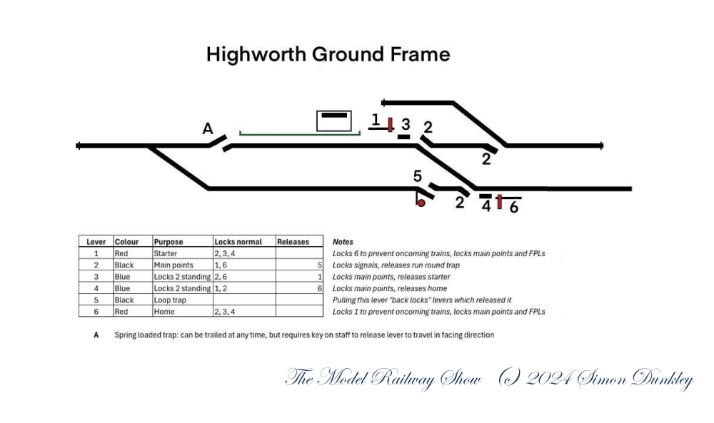
My British endeavour will provide a very different experience. My layout depicts the Edwardian Era Great Western Railway in 7mm and is inspired by the terminal at the end of the Highworth branch. Even a small branch line terminal such as this one featured an interlocked ground frame to control the turnouts and associated signals to protect the movement of passenger trains. I’ve been working with a few friends to understand how this worked, and to bring it to life on my layout.
My first shout-out must go to Simon Dunkley, a UK modeller I’ve known for many years. He has been incredibly patient with me as I ask questions about how things would’ve been arranged at Highworth. He’s found several useful resources and drawn up the interlocking diagram, which I’ve shared above. (Thanks, Simon!)
Based on our conversations, I’ve set up a bank of six slide switches to represent the various levers in the ground frame. This is located across from the location of the frame at one end of the station building:

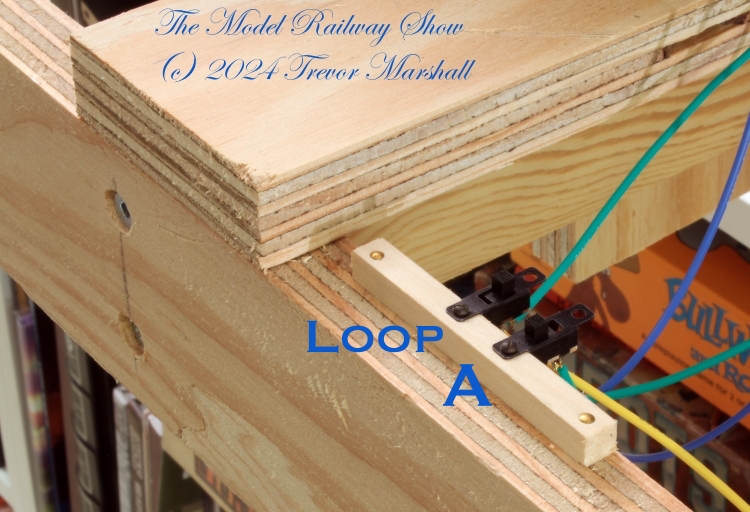
I’ve also added a two-lever frame at the far end of the run-around loop, to control the derail and turnout there:
The key word in the title of this piece is “temporary”. My little single-pole double-throw (1p2t) slide switches do not provide the proper interlocking as described on Simon’s diagram of the ground frame. However, my friend Mark Zagrodney in southern Ontario has expressed interest in building an interlocked ground frame for this layout and I’m sure not going to discourage that! We’ve roped our mutual buddy Chris Abbott into this as well. (Thanks in advance, guys!)
We determined that the best way to tackle this problem is have the ground frame act on the slide switches, which would then control the turnouts and signals in the normal manner. I’ve proven they will do the job on the layout and have sent Mark and Chris a box of the same slide switches I’ve used. When it comes time to mount the ground frame, connecting it to the layout will simply involve swapping some wires.
I’m already enjoying running trains using my temporary ground frames. This layout will provide a very different operating experience from anything I’ve built in the past – and that’s a good thing!
