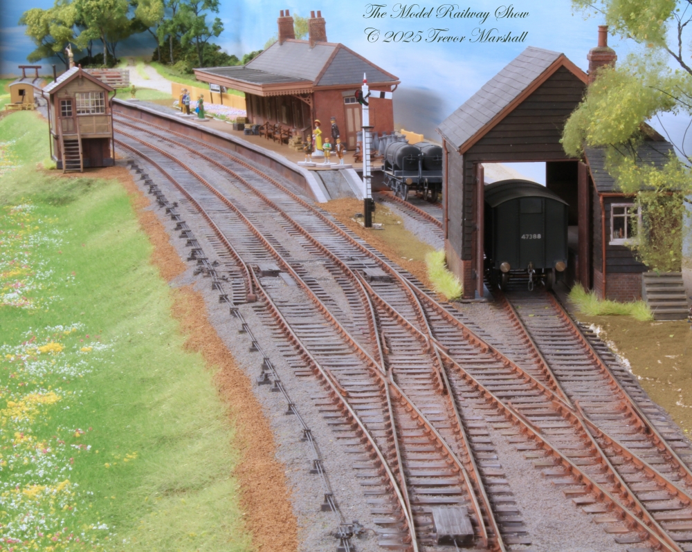
I’ve started to add scenic details to Bydemill – my 7mm scale, Edwardian era, Great Western Railway layout. Over the past few days, I’ve been concentrating on the point rodding – the pipes and other hardware that allow those in the signal box to throw switches and catch points. What I’m sharing here is the first steps – there’s more to do. So far, I’m pleased.
My signal box has four levers for trackage:
Lever 2 aligns the three switches seen in the lead photo.
Levers 3 and 4 engage facing point locks on two of those turnouts.
Lever 5 controls the catchpoint seen on the loop (leftmost track) in the lead photo.
In addition, the signal box has two levers to control signals, which are connected differently (and will be covered in a future post, once I have installed those details).
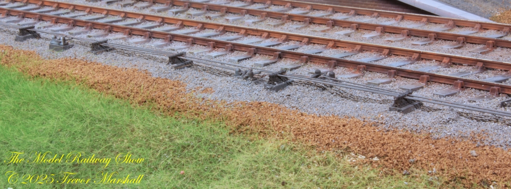
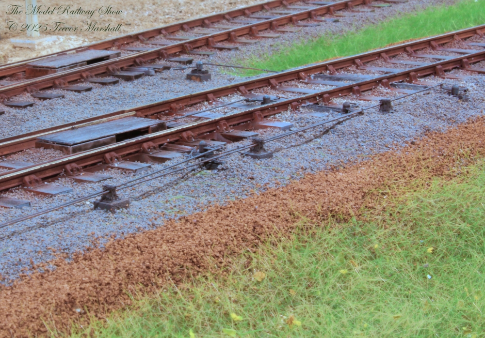
I started by determining where rods would have to pass under the trackage. I dug out the ballast between ties (and in some cases moved ties), then installed troughs made from styrene shapes. I then restored the ballast around these. Running the troughs would’ve been much easier to do before I ballasted. In fact, planning for these before I started laying track, to ensure clear runs lined up across multiple tracks, would’ve been even smarter. Lesson learned.
For the hardware, I used 3D printed parts from Modelu in the UK. Modelu offers an extensive selection and there are so many rabbit holes to go down, this could become a hobby-within-the-hobby. So before I ordered I did some planning – aided by an excellent book, Point Rodding – Prototype & Planning Notes for Modellers, published by The 2mm Scale Association. This helped me figure out where to locate the various components.
I’m pleased that I’ve located compensators halfway along the rodding runs, balanced the amount of rodding that’s pulled vs pushed, and otherwise attempted to create believable runs.
The rods are phosphor bronze wire, representing the 1.25″ diameter tubes that evolved from pipes used for gas. (This leads one to wonder why it isn’t called “Point Tubing”…)
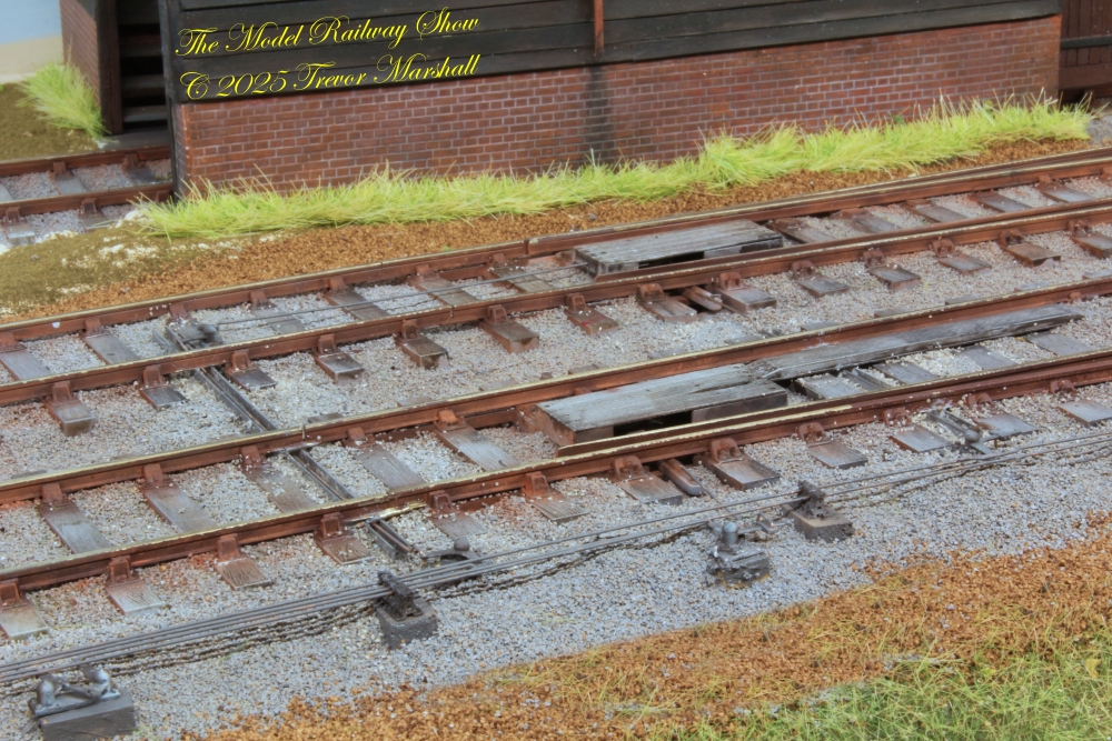
There’s more to do. I have not yet built the lead-off board – the place where the rods leave the signal box then turn 90 degrees to run alongside the track. I also have to install the cosmetic supports, pulleys, and cables to operate the home and starter signals.
Everything needs more paint and weathering. I started with darker colours and will work my way towards lighter shades. While I have the paints out, I’ll have to touch up some of the rails, too.
And I need to clean up the ballast and the cess – including sweeping errant pieces of ballast off the ties and rails.
But so far, so good!
