A friend recently asked if I had a layout plan I could share for my S scale layout based on the Niagara St. Catharines & Toronto Railway.
The short answer is, I don’t have one. At least, not the kind one expects – a hand-crafted or CAD-produced scale drawing that would be easy to scan and share.
Here’s why:
I’ve planned my version of the NS&T using prototype track diagrams. I’ve picked a series of prototype scenes to model, but have modified them – in large part, by rearranging their order to better fit the space.
From this, I created a crude general arrangement drawing that placed each element in the room – connected via a main track which, at this point, was simply a plain line with curves drawn to establish that my minimum radiuses would fit while maintaining decent aisle space, access, etc.
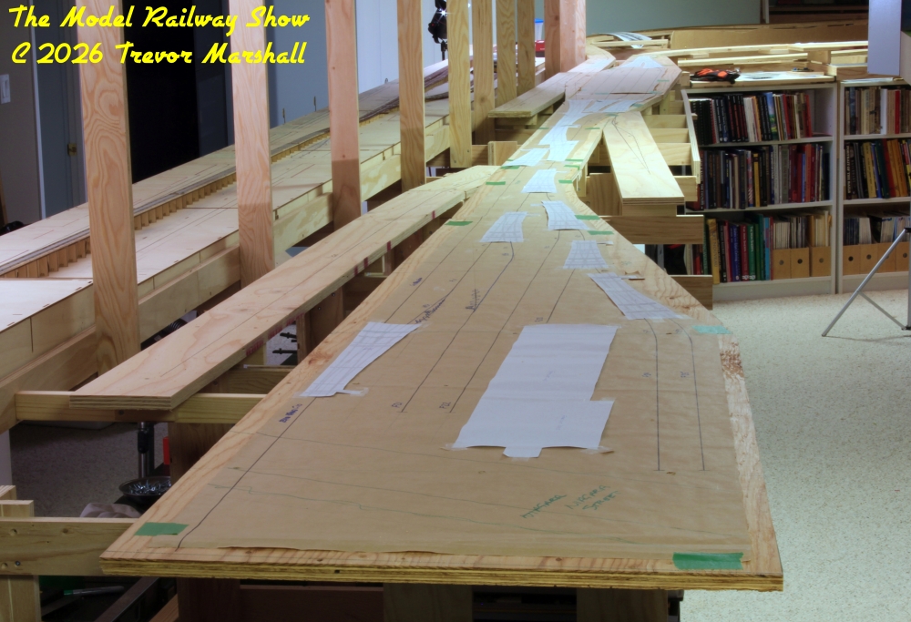
With this general arrangement in hand, I then planned each section in full size. I laid out plywood sheets to provide a base to draw on, then rolled out 24-inch wide kraft paper and drew in in a main track in pencil.
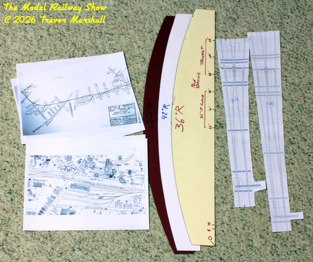
To ensure my ideas would fit, I printed out a bunch of turnout templates from Fast Tracks (an excellent resource). I labelled these (eg: “10L” to remind me this is a Number 10 left hand turnout). I taped individual templates into groupings – crossovers, yard ladders, etc. – then shuffled the groupings about on the kraft paper until I was happy with their position. If I needed to, I could lift one or more turnouts and reposition them.
I used a ruler and home-made curve templates to add the plain track that connected these groupings. I also pencilled in street crossings and – in the case of the freight shed – created a paper template of the structure so I could ensure adequate clearance around it.
Since I’m working full-size, I can use actual rolling stock models to check spur capacities, clearances, and so on.
Once I was happy with the plan, I went back and inked it using markers.
As I worked, I selectively compressed each scene – again, to better fit the space. Some CNR track diagrams from the 1970s and 1980s were handy for this exercise, as the railway had down its own compression as it lost freight business to trucks. For example, I was able to reduce the tracks in the freight shed / team track yard by looking at what trackage the CNR had pulled up, post NS&T.
The tracks that remained also highlighted for me which ones were important as yard or industry leads or to serve special purposes (for example, a ramp track), and which existed primarily to increase capacity. For the Niagara Street scene, I reduced the shed tracks from three to two, and reduced the team tracks from three pairs of tracks to one. I also eliminated a number of main tracks that ran passed the freight shed, since this scene is the end of the line on my layout.
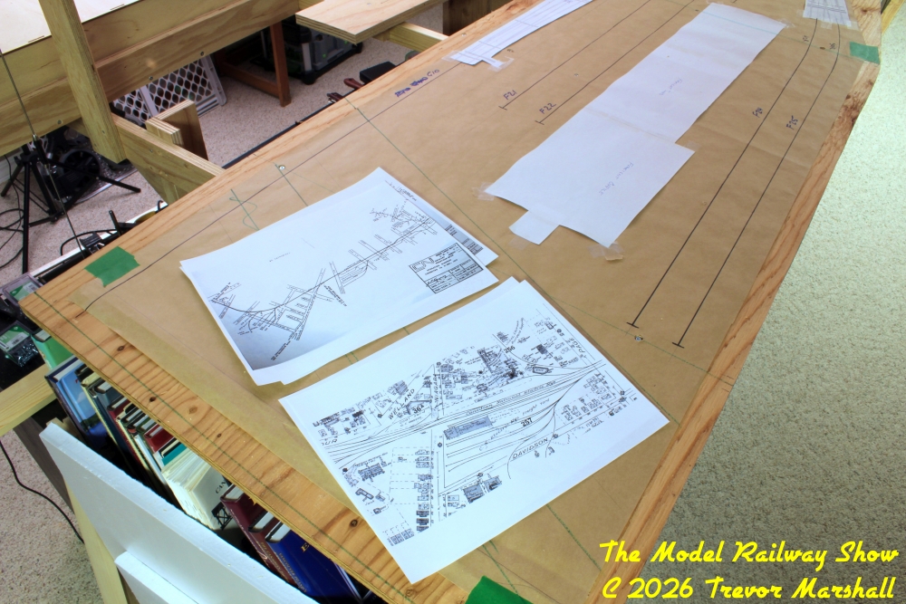
In addition to track diagrams, I’ll refer to any prototype photos I have to try to capture the look of the location. Crude mock-ups of structures can help here. Maps can also help: For example, a city map of St. Catharines helped me determine the angle at which various streets crossed the railway.
With the full-size plan completed, I cut my plywood to fit beneath it, spliced together these sub-roadbed sections, and mounted them on risers to establish grades and secure the sub-roadbed to the benchwork. While doing this, I made minor adjustments to turnout locations to ensure subterranean turnout controls would not run afoul of the benchwork framing. Typically, sliding a turnout to the left or right by an inch would suffice.
My next step will be the transfer the drawing from kraft paper to plywood. This process will largely destroy my kraft paper drawing but by that point it will have served its purpose and I can begin to lay cork roadbed and track.
Given that I know the prototypes well and have lots of information to guide me, I find this holistic approach to planing works well for me – better than small scale drawings. Your milage may vary – but if you’re having trouble planning on graph paper or on a screen, maybe this approach will work for you, too.
